Sennheiser EK3253 Specifications
Browse online or download Specifications for Noise Reduction Machine Sennheiser EK3253. Sennheiser EK3253 Specifications User Manual
- Page / 30
- Table of contents
- BOOKMARKS
- Instructions for use 1
- Contents 3
- Safety instructions 4
- SR 3254/SR 3256 transmitters 6
- Delivery includes 7
- Indications and displays 9
- RF OUTPUT 14
- Using the transmitter 16
- Display mode 19
- Setting mode 19
- Care and maintenance 22
- If problems occur 24
- Additional information 25
- Specifications 26
- Connector assignment 27
- Accessories 28
- Warranty regulations 29
- EC Declaration 29
Summary of Contents
4Instructions for useSR 3254SR 3256SR 3254SR 3256
12Preparing the transmitter for useUsing the transmitter as a stand-alone unitMounting the transmitter feetTo ensure that the transmitter cannot slip
13Rack-mounting several transmittersYou can use the supplied rack mount “ears” to mount the transmitter into a 19" rack (1 U). If you wish to mou
14Rack-mounting the transmitter and mounting the antennas to the front of the rack왘 Mount the antenna holders to the handles of the transmitter as s
15Connecting the transmitter to the mainsThe transmitter can be connected to 230 V or 115 V AC. Before you plug the mains connector into the wall sock
16Connecting the mains cable왘 Insert the supplied mains cable into the socket on the transmitter and pass the cable through the cable grip.NoteA cable
17Mounting and connecting remote antennasUse a remote antenna when the transmitter position is not the best antenna position for optimum transmission.
18Using the transmitterSwitching the transmitter on/off왘 Press the POWER button to switch the transmitter on or off. After switch-on, the LC display
19왘 First, set the volume control # to the lowest volume by turning it to the left as far as possible. Then gradually turn up the volume.
20The operating menu of the transmitterVia the operating menu, you can quickly and easily change the following settings:The buttonsIn the operating me
21Overview of the operating menuDisplay modeSetting modePress SET for 1 sec.SETSETSETCurrent channel : U 1... U 16, F 1... F16SET: Selects the chann
Thank you for choosing Sennheiser!We have designed this product to give you reliable operation over many years. Over sixty years of accumulated expert
22TUNE Selecting the frequencies to be stored in the channel bank “U”Via the “TUNE” menu, you can freely select the frequencies to be stored in the ch
23CHANNEL Selecting a channel from the channel bank “U” or “F”왘 Press the 왖/왔 buttons to select the “CHANNEL” menu. The LC dot “CHANNEL” and the “CH
24Care and maintenanceCleaning the transmitter왘 Before cleaning, disconnect the transmitter from the mains.왘 If necessary, you can clean the transmitt
25If the replacement fuse also blows, please contact your local Sennheiser agent or send the transmitter, with a precise description of the trouble, t
26If problems occur ...Error checklistIf problems occur that are not listed in the above table or if the problems cannot be solved with the proposed s
27Additional informationHDX noise reduction Progress you can hear:The product family is equipped with HDX, the Sennheiser noise reduction system that
28SpecificationsNote:The above data also apply to the second transmitter in the SR 3256.RF characteristicsFrequency ranges 518–554, 626–662, 740–776,
29Connector assignmentOverall unitPower supply 115/230 V AC +10% / –15%Power consumption SR 3254 max. 13 WPower consumption SR 3256 max. 23 WDimensio
30Accessories AC 3000-EU Active Antenna combiner Cat. no. 009424AC 3000-UK Active Antenna combiner Cat. no. 009410AC 3000-US Active Antenna combiner C
31Warranty regulationsThe guarantee period for this Sennheiser product is 24 months from the date of purchase. Excluded are accessory items, rechargea
ContentsSafety instructions ... 6SR 3254/SR 3256 transmitters ...
Sennheiser electronic GmbH & Co. KG30900 Wedemark, GermanyPhone +49 (5130) 600 0Fax +49 (5130) 600 300www.sennheiser.comPrinted in Germany
6Safety instructionsy Please read these instructions carefully and completely before using the transmitter.y Make these instructions easily accessible
7signs that you have been subjected to excessive noise for too long a time:y You can hear ringing or whistling sounds in your ears.y You have the impr
8SR 3254/SR 3256 transmittersWith the wireless in-ear monitoring system, consisting of the SR 3254 or SR 3256 stereo transmitter and the EK 3253 bodyp
9The channel bank systemThe SR 3254/SR 3256 transmitter is available in five UHF frequency ranges:Range A: 518 to 554 MHz Range B: 626 to 662 MHz Rang
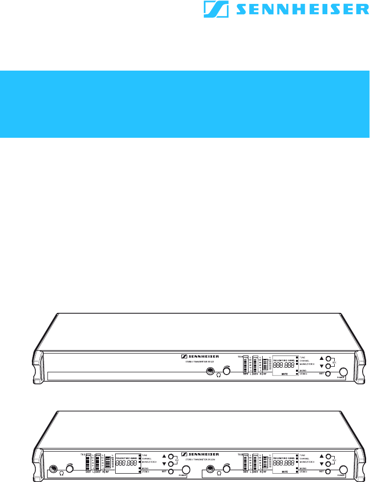
10Overview of operating controlsNote: Connections and operating controls marked with a star () in the above illustration are those for the second tra
11Indications and displays Alphanumeric display “FREQUENCY MHZ” display “CHANNEL” display LC dot CHANNEL LC dot TUNE LC dot MONO/STEREO LC dot
© 2020, manymanuals.com. All rights reserved. | 2.176 s |
 Manymanuals.com
 Manymanuals.de
 Manymanuals.fr
 Manymanuals.it
 Manymanuals.pl
 Manymanuals.cz
 Manymanuals.es
 Manymanuals-pt.com
Comments to this Manuals